

Timeless Paper on Static/Couple Balancing
7th Oct 2015
BALANCING ROTORS
USING THE STATIC/COUPLE METHOD
INTRODUCTION
The most common method of field balancing is to use the influence coefficient method of
balancing. There are times when a variation of this method, commonly referred to as
static/couple balancing, will produce a balanced rotor in a more convenient manner and
with less time. The technique can also be used with rotors that bow or deflect at rotating
speed and balancing is being performed at that speed.
The static/couple method is also used when balancing in a balancing machine. Most all
balancing machine instrumentation provides direct reading of the static and couple components
of the unbalance upon request. In the event that instrumentation is being used either for field
balancing or on a balancing machine that does not provide for static/couple balancing,
calculator and computer programs are available.
Not all instrumentation available for balancing today solves for static/couple unbalance in the
same manner, therefore a review of the instrument manual is in order prior to balancing.
Another major difference in instrumentation and computer programs is how phase is read
and displayed for correction. Some instruments display the correction angle against rotation
of the rotor while others display the correction angle with rotation. This reference system also
applies to positioning calibration (trial) weights. Be familiar with the instrumentation being used.
ISO Standard 1940/1, Mechanical Vibration, Balance Quality Requirements for Rigid Rotors,
(ANSI STD. S2.19-1975) provides a method for applying unbalance tolerances based upon
the static/couple components. This is extremely helpful and valuable when balancing narrow
plane rotors or overhung rotors in a balancing machine. Establishing a balance tolerance for
rotors of this type following the basic formulas established for symmetrical rotors, such as
motor armatures, can result in an unacceptable level of vibration when the rotor is installed.
It is recommended that a copy of the Standard on Balance Quality be purchased for reference.
Definitions relating to static/couple balancing and other selected definitions for this paper
can be found in the Appendix. These definitions are from ISO 1925, Balancing Vocabulary.
RLB070796
DISCUSSION
Any rigid rotor can be balanced in any two planes on the rotor. For convenience, most
rotors are balanced in the two planes nearest the bearing journals, since access to add
weights is usually convenient and the weights have the greatest effect on the vibration level.
This approach to balancing is referred to as the influence coefficient method of balancing.
It involves observing the original vibration occurring in a rotor, then adding calibration (trial)
weights in each of the two selected balancing planes. The result of these readings are
calculated in the instrument to give a balance weight to be added in each of the two planes.
When the rotor is being balanced in a balancing machine, direct reading of unbalance may
be available and calibration runs may not be required.
There are several type rotors, however, that have characteristics that lend themselves to a
different type of weight correction. Rotors that are dominated by static unbalance may be
better corrected by spacing the static corrections in several (or numerous) planes along the
rotor length. Narrow plane rotors normally respond better by balancing the static unbalance
first and then reducing the couple unbalance to an acceptable level.A rotor is considered as
a narrow plane rotor if the distance between the correction planes is less than 1/3 of the
distance between the bearing journals. Overhung rotors (rotors with both planes outside
the bearings on the same side of the rotor) respond well to a static correction in one plane
nearest the center of gravity and then correcting the couple unbalance in two planes.
Examples of these rotors areshown in Figures 1, 2 and 3.

|
Multi-Plane Rotor dominated by Static Unbalance
Figure 1
|
Narrow Plane (Disk)Rotors
Figure 2
|
Overhung (Both Planes Outboard of Bearings)
Figure 3
Another application where static/couple balancing improves results is in rotors that bow or
operate near their first critical speed (free- free mode). Static balance corrections placed in the
center of the rotor will reduce the bow and/or flex.
Still another example where static/couple balancing is of benefit is in reducing the vibration
level in large rotating equipment such as turbines and generators during startup and
coast down at resonant (rigid mode critical) frequencies. In general, the first resonant
frequency is associated with static unbalance and eliminating the static unbalance allows for
less force on the bearings during initial startup and/or coast down.
The amount of static/couple unbalance or the resulting vibration associated with each can
be determined by plotting the measured vectors at the rotors bearing points. Since most
instrumentation today includes this program, a vector solution in not included in this article.
DEFINITIONS
Static Unbalance is defined as that condition of unbalance where the Principle Axis of Inertia
is displaced parallel to the shaft axis. An illustration of static unbalance is shown in Figure 4. This is
the type of unbalance that when a rotor is set on a pair of knife edges, the heavy spot would roll
to the bottom. A pure static unbalance could be corrected by adding one weight in the plane
that contains the CG.

|
Figure 4
The static weight can be added in other locations provided that it is proportioned equally from
the plane that contains the CG. For example,Figure 5 shows two correction weights placed
on the rotor in planes equidistant from the plane that contains the CG, at the same radius as
the unbalance weight and each weight weighing 1/2 the amount of the unbalance weight.

|
Figure 5
The mathematics of this example would show all the Forces and Moments acting on the rotor
would be 0.
This method of correction is widely used on rotors that are made up of disk shapes,
or provisions for weight correction have been made in multiple planes. The benefits of
using this method of correction for the static unbalance is it allows for corrections more
closely approximating the unbalance condition in the rotor, keeps excessive corrections
from being made in one or two planes, and helps with a rotor operating near its bending
mode critical (1st free- free mode).
Couple Unbalance is that condition of unbalance where the Principal Axis of Inertia intersects
the Shaft Axis at the Center of Gravity (CG) of the rotor. An illustration of couple unbalance
is shown in Figure 6. If we used the same example as we did with static unbalance and placed
a rotor with couple unbalance on knife edges, it would not roll to the bottom but would appear
to be in balance.Couple unbalance can only be seen if the rotor is turning and is best described in
everyday terms as a “wobble”. Couple unbalance is two equal weights in two different planes
180 degrees from each other.
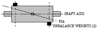
|
Figure 6
Correcting for couple unbalance differs from correcting for static unbalance in the fact that it
always requires two equal and opposite weights in two different planes. Of equal importance is
the fact that the couple unbalance can be corrected in any two planes on the rotor and need not
be referenced to the CG.See Figure 7.
|
Figure 7
The mathematics of this example would show all the Forces and Moments acting on the rotor
would be 0.
There are two other types of unbalance as defined by International Standards. These are
Quasi-static Unbalance and Dynamic Unbalance. The definitions for these can be found in
the Appendix under Definitions. They are not discussed in detail here since both can be
changed into their static and couple unbalance components.
In our examples for both static and couple unbalance, the term equal weight or weights has
been used for simplicity. Equal, in the examples, was based upon the radii at which the weights
were being added being the same, and in Figure 5, the distance from the CG being equal for both
weights. There are cases where it is not possible or convenient to add weight at equal radii
or equidistant from the CG, so a better definition of “equal” is required.
In the case of static unbalance, as long as the distance from the center of gravity times the
radius at which the weight is added times the amount of weight is equal, two or more different
weights can be used. In Figure 5, if the distance to the plane containing one weight is twice the
distance as to the other weight and the radius at which the weights are placed are the same, then
only half as much weight is required in that plane.
Couple unbalance is a little easier since the distance from the CG is not important. As long
as the weight times the radius for both weights are equal, then both portions of the couple
are equal. For example, if the radius at which one weight is added is twice the radius of the
other, then only half as much weight is required. If the radius can remain the same, the position
of the couple weights along the axis of the rotor can be adjusted by the distance between the
weights. For example,couple weights that weigh 5 grams and are 20 inches apart would
be equal to couple weights that weigh 10 grams and are 10 inches apart.
There are numerous applications for using the static/couple method for balancing. One of
the most common applications is in balancing overhung rotors.Refer to Figure 3.
There are several considerations to be made when balancing an overhung rotor. Only in
the rarest of occasions will the CG be in the exact plane where the static weight is added.
See Figure 8.

|
Figure 8
In Figure 8, the Static Correction Weight added to the rotor is not in the plane that contains
the CG by the dimension (x) . When this happens, a small couple unbalance is introduced into
the rotor by the static correction weight. This will cause a change in the original couple reading
even if the static reading is 0 after correction. The normal practice for balancing under these
conditions is to balance for the static unbalance first, then correct for couple unbalance.
Normally, the static unbalance will require a trim correction followed by a trim correction to
the couple unbalance.It is possible to make the static correction as well as the couple correction
for unbalance and make them in the same planes of correction. This technique is used when
knowledge or experience with specific rotors aids the correction process. Some turbine and generator
balancing will use this technique.
UNBALANCE TOLERANCES FOR STATIC / COUPLE BALANCING
When Field Balancing, acceptable balancing is related to the vibration level.If the vibration
level is acceptable, the balance level is acceptable. When balancing in a balancing machine, a
guide is required that equates the level of unbalance in the rotor to what will be an acceptable
vibration level when the rotor is installed and operating in its own environment. The most
widely used guide is the ISO Standard referenced earlier.
It is important to review ISO Standard 1940/1 for an unbalance tolerance when using the
static/couple method of balancing in a balancing machine. The shape of a rotor dictates the
unbalance tolerance and becomes a large factor at the extremes of rotor dimensions. For
example, if the normal unbalance tolerance for a symmetrical rotor is applied to a narrow
plane rotor (Figure 2), the resulting couple unbalance may be 5 to 6 times better than
required. This can result in excessive removal of metal or addition of more weight than is
required to achieve acceptable forces at the bearings due to the couple unbalance.
In the same manner, the static unbalance in an overhung rotor requires the unbalance tolerance
be reduced at the major load carrying bearing to achieve acceptable forces on the bearings.
This Standard presents methods for allocating a calculated unbalance tolerance fora standard
symmetrical rotor to a rotor that requires static / couple balancing. An example of the difference in
the tolerance will be shown in the following examples.In the examples shown, the rotors all
weigh 50 pounds, the operating speed is 3600 RPM and the unbalance level required is G 1.0
from the ISO Standard.
|
Symmetrical Rotor
Figure 9
From this example, the unbalance tolerance (Uper) can be calculated from the formula,
Uper = 170 x G x W/N (in gram inches)
whereG = to the unbalance tolerance level desired
W= weight of the rotor in pounds
N= operating RPM of the rotor
170 is the multiplier required to make everything come out right
As stated, in our example, G =1, W= 50 pounds and the operating RPM is 3600.
therefore Uper(total) = 2.3611 gram inches for a symmetrical rotor, or 1.18 gram inches
per plane.
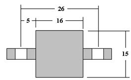
Applying the tolerance to a narrow plane (See Figure 10) and overhung (See Figure 11)
using the static/couple method of balancing requires several formulas for allocating the
unbalance tolerance based on the rotor dimensions. These formula are found in the ISO
Standard and are as follows:
Ustatic =Uper/2 x d/2c
Ucouple = Uper/2 x 3d/4b (per plane, 180 degrees apart).
where Uper is the calculated permissible unbalance for a symmetrical rotor
b = distance between the couple correction planes
c = distance to the static correction plane
d = distance between the bearing journals
|
Figure 10
In the narrow plane example in Figure 10
Uper = 2.3611 gram inches (See symmetrical rotor example)
b = 2.5 inches,c = 12 inches,d = 24 inches
Calculating the static and couple unbalance tolerance from the formulas;
Ustatic = Uper/2xd/ 2c
= 2.3611/2x24/(2 x 12)
= 1.18 gram inches for the static unbalance tolerance
Ucouple = Uper/2x3d/4b
= 2.3611/2x(3 x 24)/(4 x 2.5)
= 8.496 gram inches (two weights 180 degrees apart)
As can be seen from the example, the couple unbalance tolerance is considerably higher than
the tolerance applied for a symmetrical rotor.The reason for this is that the forces generated at
the bearings from a couple unbalance on a narrow plane rotor are extremely low.The practical
application for this type of correction is that excessive removal or addition of weight to meet
the symmetrical rotor unbalance tolerance is not required to reduce the forces at the bearings
to an acceptable level.

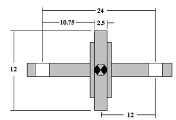
|
Figure 11
In the overhung rotor example in Figure 11
Uper = 2.3611 gram inches (See symmetrical rotor example)
b = 12 inches,c = 28 inches,d = 20 inches
Calculating the static and couple unbalance tolerance from the formulas;
Ustatic = Uper/2xd/ 2c
= 2.3611/2x20/(2 x 28)
=0.421 gram inches for the static unbalance tolerance
Ucouple = Uper/2x3d/4b
= 2.3611/2x(3 x 20)/(4 x 12)
= 1.475 gram inches (two weights 180 degrees apart)
The important observation in this example is that the static unbalance tolerance is significantly
lower the unbalance tolerance calculated for a symmetrical rotor to achieve a satisfactory
reduction in the forces at the bearings, especially the inboard bearing.
When balancing in a balancing machine, an overhung rotor is often balanced on an arbor
between bearings for convenience. When this is done, the unbalance tolerance calculated
from the dimensions of the rotor as it is used in service should be used to calculate the
unbalance tolerance.
SUMMARY
The use of the static/couple method of balancing in field balancing should be used with some
type rotors, especially rotors dominated by static unbalance, narrow plane rotors and overhung
rotors to reduce balancing time and improve the results. Other applications include reducing the
flex or bow in rotors and reducing the vibration level at resonance frequencies, especially those
associated with static unbalance.
When using the static/couple method of balancing in a balancing machine, it is important to
apply ISO Standards properly to establish realistic tolerances for both the static and the couple
unbalance.
Most of today’s instrumentation includes the ability to display both the correction as well as the
vibration level in a static/couple mode. If not, computer programs and calculators are available
to perform this function. Please review the manuals with the instrumentation to determine
the phase reference system used. Placing correction weights with or against rotation differs from
instrument to instrument.Specific procedures to solve for static/couple unbalance are available
for certain instruments.
APPENDIX
DEFINITIONS
The following definitions are from ISO 1925, Balancing Vocabulary .This Standard contains
a more complete listing of definitions and a copy is recommended for reference.
Center of Gravity (CG): The point about which a rotor’s weight is equally distributed.
Principal Inertia Axis: A line about which the rotor’s weight is equally distributed.The
CG is always on the Principal Inertia Axis.
Static Unbalance: The unbalance is distributed equally from the CG and on the
same side of the rotor.The PIA is displaced parallel to the shaft axis.
Couple Unbalance: The unbalance is at an equal distance from the CG but on
opposite sides of the rotor (180 degrees apart). The PIA is at
an angle to the shaft axis and intersects at the CG.
Quasi- Static Unbalance: The unbalance is distributed in a manner that the PIA intersects the
shaft axis at a point other the CG.Quasi-static unbalance is a
combination of static and couple unbalance
.
Dynamic Unbalance: The unbalance is distributed in a manner that the PIA is not parallel
to and does not intersect the shaft axis.Dynamic Unbalance is a
combination of static and couple unbalance.
Correction Plane: Any plane perpendicular to the shaft axis where balance
corrections are made.
Calibration Weight: A weight attached to a rotor to determine the rotor response.
Also referred to as a trial mass, trial weight and sometimes a test mass.
Field Balancing: The process of balancing a rotor in its own bearings and
supporting structure rather than in a balancing machine.
Narrow Plane Rotor: A rotor where the distance between the correction planes is less
than 1/3 the distance between the bearing journals.
Overhung Rotor: A rotor where both correction planes are outside the bearing journals and
on the same end of the rotor.
Although C D International, Inc believes reasonable efforts have been made to ensure the accuracy of the information contained in this document, it may include inaccuracies or typographical errors and may be changed or updated without notice. It is intended for discussion and educational purposes only and is provided "as is" without warranty of any kind and reliance on any information presented is at your own risk.